
Electronics ABC
Capacitors, Part 3 "Ceramic Capacitors [2]"

Key Takeaways
1. Multilayer ceramic chip capacitors (MLCCs) exhibit several key properties—rated voltage, leakage current, tan δ (Q), thermal behavior, DC bias, and impedance response—that determine proper selection and performance.
2. The rated voltage defines the maximum continuous voltage the capacitor can safely withstand; exceeding it risks insulation breakdown.
3. Leak current is minimal in MLCCs thanks to their high insulation resistance, but rises sharply once the applied voltage exceeds the limit.
4. Tan δ (loss tangent) measures dielectric and resistive losses; its reciprocal, Q, reflects quality at high frequencies—the higher the Q, the lower the loss.
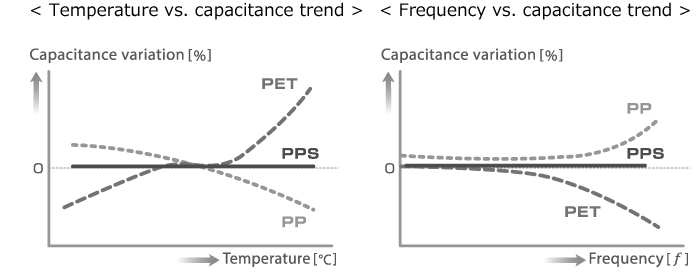
5. Thermal characteristics of capacitance depend on dielectric type: Class 1 (low εr) materials offer stable values; Class 2 (high εr) provide higher capacitance but greater temperature dependence.
6. DC bias effects cause noticeable capacitance drop in high-dielectric ferroelectric types (e.g., BaTiO₃), particularly in miniature components.
7. Impedance–frequency behavior follows a V-shaped curve: impedance decreases with frequency until the self-resonant frequency (SRF), then rises as the device behaves inductively.
8. Selecting capacitors with appropriate voltage rating, dielectric class, and SRF margin ensures reliable operation in both analog and high-frequency circuits.
Major characteristics of multilayer ceramic chip capacitors
In order to use capacitors correctly, it is important to understand their particular characteristics. This section explains some of the main features of multilayer ceramic chip capacitors.
●Rated voltage
Every capacitor has a certain limit to the voltage that can be applied to it. The rated voltage refers to the maximum voltage that can be applied during constant operation without causing a problem. Normally, the rated voltage is given as a DC voltage, but for some products, an AC voltage may also be given as a guaranteed value.
●Leak current / insulation resistance / insulation breakdown
Although a capacitor in principle blocks DC current, a slight leak voltage does in fact occur. The insulation resistance is a value that is obtained by dividing the current flowing in the capacitor by the applied voltage. Because multilayer ceramic chip capacitors have a high insulation resistance, leak current does not present a problem in normal applications. However, when the rated voltage is exceeded and the applied voltage is increased further, the capacitor will be subject to insulation breakdown at some point.
●Tan δ (tangent delta)・Q
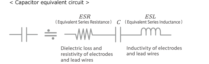
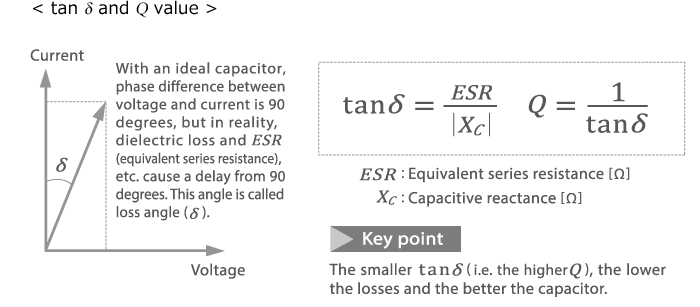
Ideally, a capacitor used in a circuit should not consume any energy, but in reality, factors such as dielectric loss of the capacitor and the resistivity of electrodes and lead wires (known as ESR: equivalent series resistance) cause an energy loss. This manifests itself as a phase shift in the current flowing in the capacitor. The phase difference between the voltage applied to the capacitor and the current ideally is 90 degrees, but the abovementioned loss causes a delay beyond 90 degrees. The angle δ (loss angle) of this delay when expressed with the trigonometric tan function (positive number) is referred to as tan δ (tangent delta) or dielectric tangent. The reciprocal of tan δ is known as Q (quality factor) which is an index for the performance of a capacitor in the high frequency range.
●Thermal characteristics of capacitance
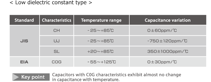
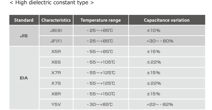
Multilayer ceramic chip capacitors used extensively in electronic devices can be divided into two major categories according to their type of dielectric, namely (1) low dielectric constant type, and (2) high dielectric constant type. These can be further subdivided by thermal characteristics, a specification that is governed by JIS (Japanese Industrial Standards) and EIA (Electronics Industries Association in America) standards.
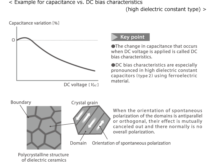
●DC bias characteristics (DC voltage characteristics)
The capacitance of a ceramic capacitor also changes according to the applied voltage. With a DC voltage, this property is referred as the DC bias characteristics. With low dielectric constant capacitors (type 1), capacitance hardly changes, but in high dielectric constant capacitors (type 2) with "B" characteristics and especially ceramic capacitors with “F” characteristics, the change is significant. This is due to the fact that high dielectric constant capacitors use a ferroelectric substance (such as BaTiO3) which generates spontaneous polarization.
Ceramic material is a polycrystalline substance that consists of a large number of crystal grains. In ferroelectric material, the so-called domains of these grains are arranged alternately in the opposite direction, thereby canceling each other out, so that no polarization occurs. As the strength of the applied direct electric field increases, the dielectric constant initially also rises because the orientation of spontaneous polarization is aligned with the orientation of the electric field. However, when the electric field is made stronger, alignment ceases and saturation is reached, causing the dielectric constant to drop. When applying DC bias, it is therefore necessary to select the correct parameters taking the characteristics of the dielectric as well as the usage voltage and withstand voltage into consideration. Also, the capacitance drop caused by DC bias will tend to be more pronounced in smaller capacitors.
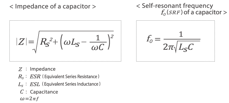
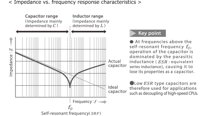
●Impedance vs. frequency response characteristics
The higher the frequency of an alternating current, the more easily it will pass through a capacitor. In an ideal capacitor, as the frequency increases, impedance will tend ever closer to zero, but in reality, there exists a frequency boundary beyond which the impedance of the capacitor will rise again. Therefore the impedance vs. frequency response curve will have a V shape (or U shape). This is because the ESL (equivalent series inductance) of the capacitor forms an LC resonance circuit with the capacitor. The frequency at the bottom of the V curve is called the self-resonant frequency (SRF). Up to this frequency, the capacitor functions as a capacitor, but in the frequency range above it, it functions as an inductor. The Q value also drops and becomes zero at the self-resonant frequency. Therefore parameters must be selected in such a way that the capacitor operates below the self-resonant frequency.
Conclusion
Multilayer ceramic chip capacitors are fundamental yet complex components whose behavior depends on voltage, temperature, dielectric composition, and frequency. Understanding parameters such as tan δ, DC bias, and self-resonant frequency helps engineers match each capacitor to its role—whether in power smoothing, signal coupling, or RF filtering. TDK’s material innovations and precision layering processes allow stable, miniaturized MLCCs that maintain performance under demanding voltage and frequency conditions.
FAQ
Q: Why can’t capacitors handle unlimited voltage?
A: Every dielectric has a breakdown limit. Above the rated voltage, electric field strength exceeds material tolerance, leading to insulation failure and short-circuit risk.
Q: What does tan δ indicate in a capacitor?
A: It represents energy loss due to dielectric and ESR effects. A smaller tan δ (and hence higher Q) means better efficiency and less heat generation, especially in RF circuits.
Q: How does temperature affect ceramic capacitors?
A: Type 1 dielectrics (like C0G/NP0) maintain nearly constant capacitance over wide temperature ranges, while Type 2 (X5R, X7R, Y5V, etc.) vary significantly as their permittivity shifts with thermal polarization.
Q: What causes the DC bias effect?
A: In ferroelectric ceramics, spontaneous polarization domains align with the electric field, initially boosting permittivity. At higher fields, saturation occurs and effective dielectric constant—and thus capacitance—drops.
Q: How does miniaturization influence DC bias behavior?
A: Smaller capacitors have thinner dielectric layers and higher internal fields, amplifying the bias-induced capacitance reduction.
Q: What is self-resonant frequency (SRF) and why does it matter?
A: SRF marks the transition where parasitic inductance (ESL) cancels capacitance. Above SRF, the device behaves like an inductor, so designers must ensure operating frequency stays below it.
Q: Can MLCCs be used at very high frequencies?
A: Yes—but only below their SRF. Choosing low-ESL structures or smaller packages extends usable frequency range.
TDK is a comprehensive electronic components manufacturer leading the world in magnetic technology
Share Share this article
RecommendedPeople who viewed this article also viewed here
Electronics ABC
Capacitors, Part 4 "Film Capacitors [1]"
Electronics ABC
Capacitors — Part 5 "Film Capacitors [2]"

Bridging the Past, Present, and Future of Tech
Informational Guide: Data Center (DC) Architecture — Definition, Layers, and Role in Modern Infrastructure
PickUp Contents